Monday, January 27, 2014

Brain training

I think I've found a possible approach to solve the issue with the coupler / adapter for the motor and transmission:
  1. I require a shaft for the motor. On one side it has to be splined (the half that goes inside the motor) and smooth on the other side with a key shaft (the part that sticks out).
  2. On the part of the shaft that is outside the motor, I'll attach a taper lock (aka quick detach bushing).
  3. A washer between the motor and the taper lock will keep the turning parts away from the Motor front.
  4. On the transmission side, I'll use the inner part of the clutch disk to attach a machined ring to it.
  5. The machined ring and the taper lock will be connected with bolts.
  6. A 20mm thick adapter plate will be machined for the motor and one 20mm thick plate will be machined to fit the bell housing of the transmission - both aluminum.
  7. The motor will be mounted to the transmission, both placed upright and then I'll spin the motor at different speeds and with minor adjustments, I'll try to get rid of misalignments / vibrations.
  8. Once the vibrations are (hopefully) gone, the two plates are clamped together, some holes will be drilled and the plates bolted together to lock them in place.
The taper lock on the motor shaft and the washer will make sure, the shaft doesn't move inside the motor. The motor shaft touching the transmission shaft ensures that it doesn't move out of the motor. So the coupler is fixed laterally although it's not tightly attached to the transmission shaft. There's some room for imperfection because the nut in the clutch disk isn't a perfect fit on the transmission shaft. So the whole connection is not a tight fit between the motor and the transmission. Hopefully this prevents damage to the motor's bearings and splined shaft.

So the only custom built parts should be the motor shaft and the adaptor ring. But as they're pretty simple, I think it won't be too expensive. Hopefully I can get the measurements of the bell house from Ford. This would help a lot to align the two parts precisely.

Saturday, January 18, 2014

It's cold in the garage

It's been awfully quiet here for a while - my apologies. I was changing jobs and going on a 6 week holiday in Australia with my family. This all needed some preparation and consumed some of my limited spare time.


So, in the meantime I was mainly doing dome rust treatment in the engine compartment. Wait a moment, rust in a 5 year old Volvo? Well, yes.. while working under the car it slowly dawned on me that I was working on a Ford and not on a Volvo. Almost every part of the frame is labelled "FoMoCo" - Ford Motor Company. And guess which were the only parts which had rust on them? Yes... kind of disappointing. But at least they stand up to it by labelling them.
I used a wire brush in a drill and removed the rust as good as possible. In accessible areas down to the bare and shiny metal. Then I applied 2-3
layers of Noverox (rust converter/primer) and 2-3 layers of black color.

Aside from that I was playing with the electronics of the car. It turned out that it was fairly easy to trick the ECU into not reporting any error on the dash. When I connected the throttle control unit (motor with two pots which report the throttle position), I only had to switch on the ignition and the throttle opened and closed completely when depressing the throttle pedal. Perfect, that's all I wanted. It looks all too good at the moment but my hopes raised considerably that I'll be able to use the CAN bus signals to control the power output of the electric motor - hence drive the car with precision throttle input and the ability to use stock cruise control. So I finalized the GEVCU module which requests the throttle position from the ECU and processes the CAN bus signal into another CAN message which controls the Brusa inverter. It all works fine - with the car on the lift.
Oh yes, and while it's hanging on there, more and more dust accumulates on the surface. It almost looks like one of those long forgotten vintage cars in an old shed. I have to move on a bit quicker. I want to get it rolling again until spring time.

One thing I discovered while playing and researching was that the generator of the ICE communicates via LIN with the ECU. As soon as the generator is ready to power the car, it signals the ECU and the ECU in turn notifies the climate control system that it's ok to enable consumers like seat heating, supplementary heating and rear window de-mist. As long as the signal is missing, none of these appliances will work. So either I have to find the CAN message spoof it or I have to immitate the LIN communication from the generator. Either way won't be that easy, I suspect. If anyone knows more about the LIN signals or how to connect a small microprocessor to the ECU, I'm all ears and would appreate some help.

Last but not least, my batteries arrived - yeeehaaa !! I ordered them from www.lithiumstorage.eu which is located in Zurich Switzerland, not more than 40km away from my garage. Good price and great service. I ordered 120 CALB CA100 cells and they arrived within a week at my doorstep. No import taxes and transport was almost free compared to international options. So one of those days I came home from work and there it was, the stack of 6 boxes with a net weight of 408kg. Holy moly! How am I going to fit this in the car ?!? :) Well, some have to go into the engine compartment, some in the exhaust tunnel under the car, some where the gas tank was and some where the spare tire would be.
If this is not enough, the rest will eat up some space in the trunk. There's going to be a lot of construction work to be done for the battery boxes.

Another thing that keeps my mind occupied is the adaptor for the motor. Originally I planned to attach the stock flywheel and clutch onto the motor - as it is most common for custom conversions. But I got serious doubts that it's a good idea to let the bearings in the Brusa motor to support the 20kg of the clutch. There'd be quite some shearing forces without the wheel supported outside the motor. Christian from www.turn-e.de told me that he did the conversion without a clutch and now uses the clutch pedal to control regen. What a great idea! I was always thinking about where to
put a lever for additional regen. Dumping the clutch also saves me from aligning it horizontally to get it working. My currently favoured approach are two-plates: one 2cm thick which perfectly fits the motor, the other als 2cm thick which fits onto the gearbox. The gearbox has two precision dowels to position the ICE. This second plate is made to fit the dowels and lock it into relative position to the gearbox. Then we will place the motor with its plate on top of the other plate (vertically) and let it run. With small adjustments it should be possible to eliminate all vibration caused by misalignment. Once the motor and the gearbox are aligned, the plates are clamped together and then locked down with a few very strong bolts. This way it should be possible to remove the motor and precisely put it back in place again without much effort.
The adapter between the involuted spline shaft of the motor and the shaft of the gearbox is going to be another challenge. I'm thinking about two shafts - one in the motor and one around the gearbox-shaft. They are connected via a flange. But honestly, I'm a bit at a loss here. Anyone got some experience with this or a hint?

Not much know-how to share for the moment.. I hope this changes in the next post.

Wednesday, August 14, 2013

The ICE age is over...

After about 5 evenings/nights (5x 4-5h) spent in solitude with the S80 I convinced her (and myself) that it's about time to pull the tooth that was already loose for several weeks:
  • The coolant and the transmission oil was removed
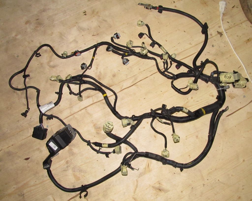
  • The engine cable tree had to go out
  • All tubes were removed, incl. the hydraulic line of the clutch
  • Gear shifter was removed from transmission
  • Gas lines removed
  • Gas tank was removed - that was an adventure in itself

Gas tank
The tank was held in place by two brackets. At 23:00 in the night no one could be called for support, so I had to do it on my own or wait. Well, who am I to give up at 23:00 already? So, first remove the left bracket and then hold the tank in place with one hand. There were still about 8 Liters of gasoline in it. By lowering the lift a bit, I was able to use not only one hand to support the tank but also my head. Knowing that there might be some wires and tubes still attached on the upper side of the tank and that I won't be able to go to the workbench to get some tools, I stuffed all I could possibly need into my pant pockets beforehand: several sizes of screwdrivers, knife, pliers. While still holding the tank in place, I removed the second bracket. As soon as it was gone, a hideous balancing act started with the gasoline wavering around, continuously shifting the center of gravity. By various acts of gravity defiance, I managed to remove 2 plugs and one tube and then the tank was free.

Engine
A friendly shop owner in our little town lent me his motor lift. The removal went fairly well. The motor got stuck one time because the transmission hung a bit low. The lift didn't go as high as it should have. So alike to the gas tank removal, I had to use two hands to lift the sagging transmission high enough to get it over the front of the car and one foot to get the motor lift moving backwards. Looked and felt criminal but it worked :)

Transmission
Removing the transmission from the engine was a quick jobs: 10 screws, a few strong pulls and it was separated. But looking at the service manual on how to remove the clutch was a bit a downer. Because it's a self-adjusting clutch you have to use a special tool to relieve the tension of the springs to remove it from the engine and mount it again. Well, just another obstacle. I'd appreciate any hint on where to get this (and keep it for several weeks)
I'm already giving a possible mounting frame some thoughts. I'll have to gather some know-how on how to support the rear end of the motor, how to support the right driving shaft and how to counter torsion forces when accelerating or using regen. The support for the driving shaft has to be fixed with the motor/transmission assembly. Any change in the angle between the transmission and the support of the long shaft has to be avoided.

Shopping
I dared to do some more shopping: a 300€ can-usb interface from peak systems in Germany - apparently the only way to configure the Brusa components and to do some first tests (and protocol sniffing). And a 100€ 12V Bosch water pump as it's not advisable to operate the water-cooled Brusa components without any coolant circulation.
What else is missing? Some tools to crimp wires (12V and HV) and of course the car grade 12V and HV cables. I'd like to buy some HV cables but don't know how much yet. Would I just cut long pieces for first tests which I could re-use and shorten on one end for the final build?

GEVCU
The motor controller for the Brusa DMC5 is under way. It's ready to receive some status messages and log them to the console. For further development I need to do some tests with the real thing. That's why I bought the USB-CAN adapter from Peak-systems.com. I'd say it's about 20% done..


Sunday, August 4, 2013

A lot going on in parallel


Finishing the shop/garage
The old floor of the wood shed was in a very bad shape and you certainly could not place a car nor a car lift on it without arriving one floor deeper with the whole equipment. So a new floor had to be laid by the carpenter. In the area of the lift we took a 5cm thick triple layered wood panel - it's sturdy enough. The two columns of the lift were placed directly onto the 20cm thick wall of the cellar.
Car lift problems
After the car lift was mounted, it worked - but only for 1sec, then
the fault current protection (FI) cut the power - once even a bright and loud spark shot out of the control box (relais). After measuring the resistance of the control box towards ground and then the motor phases it became evident that there's a ground leakage in the direction of the motor. Opening the wire-box at the 30 year old motor quickly revealed to problem: rotten wires and isolations touching the box frame. I replaced the worst connections and fixed the isolation problem with heat shrink tube. And voila, the lift works and raises the car in half a minute :)

A first glance under the car
Once the car was safely up in the air, I was able to take a first look at what's expecting me. Not all too bad - only some rust on the frame which needs to be taken care of one day.
Interesting is though that all parts of the frame are labeled FoMoCo. After having read about Volvo using the frame of a Ford Mondeo, it quickly became evident what the meaning of that is: Ford Motor Company.
Removing the engine
Now that the shop is ready, it's about time to take out the internal combustion engine. First the air filter, the ECU, some tubes and then the wheels, the cat, some covers and the lower control arms to be able to remove the axles. Well, these control arms.. you should be able to simply pop the rubber out of their joints (near the wheel). But no greasing, no force, nothing I could figure out made this %*"*-things pop out. Not even the original Volvo removal tools (lent from a friendly garage nearby) were of any help. I even attached a 7cm thick pipe to the arm and with two persons (2x80kg) hanging at the end of the pipe we were only able to bend the pipe! So I gave up and removed the control arms on the other end - where they're attached to the frame with three rusty and very hard to remove screws. But it worked and I was able to remove the axles from the wheel disc.
Unfortunately I pulled a bit too hard on the short axle to get it out of the gear-box and broke something in it (150.- repair costs). But I'm happy to report that almost everything is disconnected from the engine now and it is supported by two screws and the coolant tubes. Almost ready to be taken out ! :)
 

Lightning strike
While I was working in the shop one night, a thunderstorm approached. As one strike was quite close (about 1km away), I quickly unplugged the laptop and stereo. A few seconds later: white flash and kaboom at the same moment. "That was close!" I thought. Well, it was: it hit our house 5m next to the shop where my wife and kids were sleeping. Result: cover cap of the heating temperature sensors flew 10m away from the house, all fault current protectors triggered, 24-port switch: gone, stereo: gone, sat system: gone, phone distribution box: fried (copper was vaporized from circuit board !). Hopefully not a bad sign but rather the provisioning of enough electricity. But: My little boy (5y) slept like a baby and did not wake up at all - astounding ! :)


Coding for GEVCU
Also a lot of coding was done for the GEVCU project (General Electric Vehicle Control Unit). Collin Kidder laid a great base in the first version of the ArduinoDue program. But the motor controller and throttle was hard coded and referred to everywhere in the code. I introduced handler classes for the CAN bus and the Due's three timers to add some abstraction and de-couple the components. Now all components/devices which are added to the GEVCU can register themselves as observers to the CAN bus or a timer and receive triggers from their respective handlers.
Also a first implementation for a CAN based throttle was added based on my previous prototyping (see previous post).
All this coding was necessary to lay a solid base where I can start implementing the motor controller for the Brusa DMC5 inverter. The GEVCU will in the end query the original ECU of the car for the requested throttle and then convert it into a torque request for the inverter. Of course it will also perform all the necessary steps to get the the devices into an operable state and also handle stuff like regen.
Jack Rickard and his evtv team are currently rigging up a VW Kübelwagen (the "Thing") which is already equipped with a DMOC inverter and a Siemens motor (from Azure Dynamics). During the EVCCON 2013 which is about to start next week, they're trying to get it running with the GEVCU (which is still in alpha phase - so not everything might work out as expected).

Pick-up of Brusa Items - or X-Mas in May

Sorry, long time no updates.. (I've been busy though)

I was able to pick-up the Brusa components in Sennwald Switzerland. During my visit I was given a thorough tour through the factory which was quite impressive.
I also started my ventures into analyzing CAN bus messages and to find out how to query the ECU for the requested throttle position so it could be used to send commands to the Brusa motor controller.

I made a short video about this for http://evtv.me . It appeared in the show of 14th of June 2013. Here you'll be able to watch it directly (first some introduction, then CAN bus analysis and at the end some impressions from the Brusa components pick-up) :
 
 
The code for the CAN-Monitor and the CAN-Throttle prototype can be found here: https://github.com/neuweiler/CANMonitor and here https://github.com/neuweiler/CANThrottle (might give an idea how to use the ArduinoDue as a CAN monitor).


next steps:
  • Refactoring of GEVCU to be more modular and support the addition of other motor controllers and throttles
  • Finish the shop and set-up the car lift
  • Start to take her apart ;)

Sunday, May 5, 2013

Springtime

Last weekend was quite a busy one EV wise:
  • I picked up the used car lift from Jäggi Autolift and unloaded it to the wood shed. A minor mishap was the placement of the wood planks to prevent the forklift from sinking in. It was quickly remedied with the help of my father-in-law. ;)


  • The sponsoring stickers arrived and were mounted to the car by a good friend of mine:


  • I built myself a dual CAN shield for the Arduino Due as suggested in the Arduino Forum (I took the liberty to copy the working diagram). The dual CAN channels are ideal - one is going to be hooked up to the car's bus to request throttle position and the other builds a separate bus for the EV components. To make everything a bit more resistant to the harsh conditions of a car, I was "forced" to use to of this dreaded hot-glue - just to eliminate vibrations at the solder points of the wires (where they usually come lose first). BTW: I'm pretty proud at my first attempt in SMD soldering. It came out quite well - even without the help additional flux. After soldering until 03:00 in the morning, everything worked out fine in a first loopback test.

  • I also started contributing to the GEVCU project. GEVCU stands for "General Electric Vehicle Control Unit". It's a project to use a Arduino Due or Machina as a controller for any electric car with a motor controller that requires messages on the CAN bus to start-up and receive control commands (e.g. the throttle position). The prime location for GEVCU based discussions is on Jack's Forum and the source master on github. (my fork can be found here). I'm currently implementing a webserver to display status information and configure the platform via webbrowser. Also the support for a CAN based throttle is something to start with the next days. Currently the platform only supports a (dual) potentiometer based throttle.