Battery Box - Black Box


 After mounting the battery box it was time to fill it up. As mentioned in the latest post, it was filled with two levels of batteries. Yeah, I know, it's going to be hell to maintain the batteries and check for problems. But heck, that's a consistent design flaw in my conversion. Also the batteries on the bottom of the car are only reachable if I remove them starting from the rear end. Talking of these batteries on the bottom: to give them extra protection against moisture and salt water, I intend to spray the terminals with PlastiDip. This should help to prevent corrosion and is easily removable should the need arise.
Aside from loading the battery box, I also mounted an external box (grey) to hold another HV fuse. Not knowing what exactly happens when such a fuse blows, I think it's a good idea to keep them well separated from the batteries - outside of the box (still some lingering impressions from the short circuit).
The black wire you see attached with hot glue in the battery box is the wire from a temperature sensor. The sensor was glued inbetween 4 cells. It's used to ensure that the batteries are not charged below freezing point and to detect a run-away situation during use or charge. I know it's crude - but I don't like too many wires dangling around the cells and calling for other trouble.
The top level of cells had to be added row by row and pushed under the already welded on cover. The cover had to be welded on because it will go under the front cover and can't be removed anyway. The grey block you see on some pictures is a sanding block for PCB's - to get polished copper which easily accepts soldering tin. I got it from www.conrad.ch. In my opinion it's perfect to create a clean and shiny surface on the battery poles and straps. It creates some dust which can be easily removed with a handheld vacuum cleaner - no issue.
The battery box in the back is currently made out of wood aas a prototype. Here we need to bend some metal so the batteries will fit in to the spare tire compartment and use up no space at all in the trunk. I'm pretty proud that until now the only change to the structure of the car was made in the spare tire compartment. There I had to drill the only holes. Otherwise no change on the car structure was made - no hole drilled, nothing. I mounted all parts on the vanilla structure, used only existing mounting points and through holes. Cool, eh ? :)
Device Plate - Aluminum Sandwich
First I created a prototype out of an MDF plate. It was very useful because I drilled a lot of unnecessary holes and was able to experiment with the setup. It also helped getting all the details worked out at the rear of the plate, where the car - once again - shows no straight lines. Based on this template, www.fahrzeugsausbau.ch created a final plate out of an aluminum / PE sandwich plate very easily. It's very robust (unbreakable ?) and lighter than a pure aluminum plate - a good choice. The plate resides on 3 angles attached to the firewall (created out of an L-profile) and on the front on a lid which was welded earlier to the battery box. Even fully loaded with all the devices and thanks to routing the wires and cables at the back of the plate, I'm now able to lift the plate about 20cm at the front and get access to all the stuff below it. On the underside there was also enough space to mount the 6kW heater from a wrecked Chevy Volt. |
 |
 |
 |
 |
 |
 |
 |
 |
EHPS pump - Powerful but noisy
With the help of www.klaus-ag.ch we also got the electro hydraulic power steering pump hooked up to the original hydraulic system. It required three high pressure connections. With some makeshift (oh no, not again !) electric connections to a 12V battery, I got it running, lowered the car to the ground and kept steering happily from left to right for about 10 minutes - like a child. Don't worry, the tires are to be replaced anyway - but I left two black marks on the floor - whoops :)A quick visit to a junkyard revealed the necessary connectors for the pump so a professional installation can be made. It's interesting, the pump has an 80 Amps fuse but only 10sqmm cables (7 AWG) where all tables state for 80 Amps you'd require 16sqmm cables. Well, normal load on the pump is way below 40 Amps and I hope the guys at Volvo know that a short on a 10sqmm cable is able to blow a 80Amps fuse before melting down.
Although I bought a new one, it's well worth looking for an electric power steering pump on the junkyard. Volvo V50's and V40's after 2008 tend to have one. Make sure you get them with mounting brackets and plugs. Two things I have to say about the pump: 1) It's a bit noisy.. I hope with some rubber foam, I'll be able to make it more quiet. Otherwise the "silent e-car" will not become reality. 2) The folks at TWR suck ! It took me about 10 calls to reach the technical responsible only to be told off quiet harshly that they don't provide support for car shops. Only car manufacturers. They won't even give out a CAN matrix - for their product which I bought through official channels. Shame on you TWR !
Fuse Box - Finalization of 12V connections

To finally clean up this mess of cables you see on the left side of the car (right on the picture), I also straightend the 12V system out. Cables were shortened and connected properly to the car's 12V supply line with 50sqmm butt connectors. To hook up the auxiliary 12V battery (remember ? a tiny 9Ah motor cycle lead acid battery), I spotted an empty space in the high-amp fuse area of the engine bay fuse box (red arrow). It's always on 12V - unswitched. I installed a 50amps fuse there. Also to get the constant 12V for the contactors and other EV stuff, I located an unused place for mini fuses which has 12V without ignition on. that's what I need to be able to activate the contactors when charging.
There's another free place for a similar fuse which I'm going to use for the EHPS pump. I'll try a 70 Amps at first to be on the safe side.
 |
 |
 |
Cooling Loop - Angles and Air
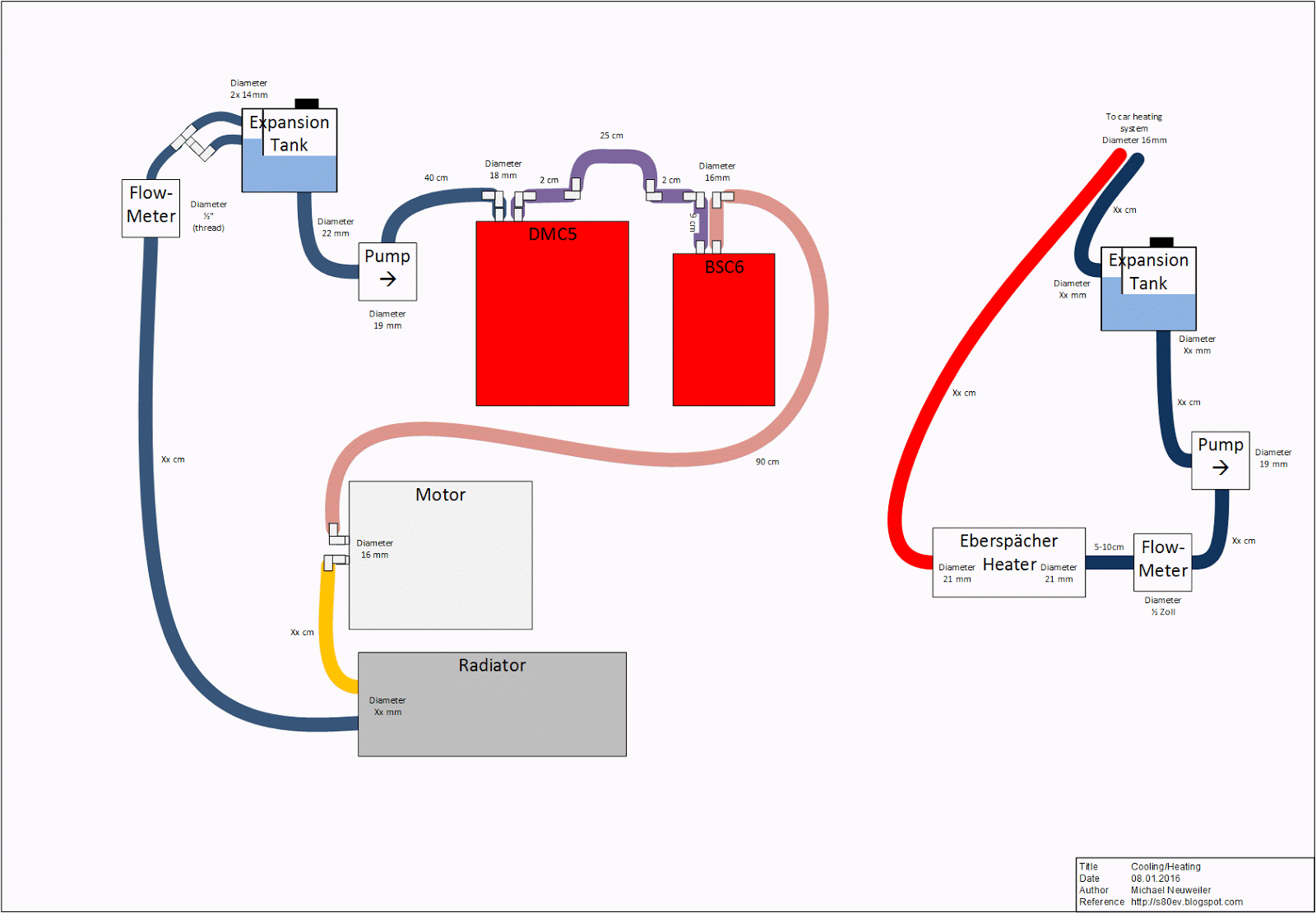

 Another thing that had to be re-done was the cooling loop. Before I just forced the hoses and they got wrinkled reducing water flow. I used 90 degree angles to get the hoses straight and prevent damage. One important change to the system is the integration of the expansion tank. Before it was hooked up with one hose only so air bubble could travel up the hose and water flow down passively. This caused a lot of effort to vent all the hoses and I had to play with the Bosch water pump a lot - which doesn't like air at all. Now in the new setup I use the two small overflow return connectors to pump the water into the tank. Due to some walls, no air should get to the outlet on the bottom. The pump is attached right after the expansion tank so once it's filled with water, no more air should reach the pump and the system will rid itself from air automatically. The only thing missing here is the radiator - here I just can't make up my mind and at the beginning I'll just use the long hose to dissipate heat in the air flow. But this won't work in summer or when driving uphills.
I use water flow sensors to monitor the flow of the coolant and especially of the water passing the heater. If not enough water passes the heater, it will be disabled immediately to prevent expanding steam destroy anything. The maximum flow rate I get at the moment is 5 liters/min. For a pump rated at 15 liters/min it's a bit low suggesting some resistance in the loop. I hope it's because of air which might still be present in some hoses with a steep angle. When driving over a couple of bumps and curves, I expect the air to vanish because from the shaking little bubbles should find their way out.
ABS - finally some snow !
 The day we had enough snow on the roads, I took the car out for a quick spin. I wanted to find out for a long time now if the anti-block-system works eventhough the ECU thinks the motor is not running (anymore). It's an absolute requirement to get the car street legal. So I was a bit anyious about it. Would I first have to fake engine signals to get the ECU running or would it work without? So I accelerated to 20kph and hit the brakes... and.. the familiar krrrrrchhchchch started - a clear sign that the ABS was working. Cool !!! :) Let's also test the anti-spin functionality by pushing down the throttle a bit harder and even here: the brake was automatically applied to the spinning wheel and the throttle was reduced. Very nice ! Well done Bosch and Volvo ! :) Me happy !
Summary - All good things come to an end
After installing some more cable protectors and the 6 temperature sensors in the battery bay/boxes, I'm re-adding the car body parts and it's really really coming to a point where I can think about getting the car street legal again. Some covers on the floor to protect the batteries from salt water, some construction foam to seal off the more complicated areas and to hold the batteries in place.. and we're good to go. Even if I'm required to have a working heater, I could get that up and running in a breeze: the code is ready, the heater installed, the pump is available... only a couple of hoses, a connector for the pump and an expansion tank are missing... compared to the rest: peanuts ! :)It's funny, you might think "finally" - me too of course - but in the recent weeks, I was just in a mode "get into it and work late on the car during the week". It hit me once late at night that it's coming to an end while I was looking for things to work on. From rear to front, it was hard to make out anything. All cables are securely attached, everything is getting nice and tidy.. it's really surprising when you're in some kind of routine to realize it's about to change. :)