Wednesday, August 14, 2013

The ICE age is over...

After about 5 evenings/nights (5x 4-5h) spent in solitude with the S80 I convinced her (and myself) that it's about time to pull the tooth that was already loose for several weeks:
  • The coolant and the transmission oil was removed
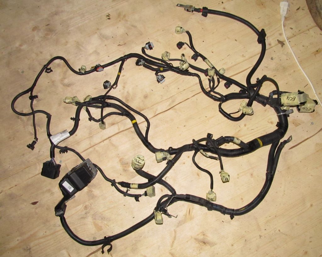
  • The engine cable tree had to go out
  • All tubes were removed, incl. the hydraulic line of the clutch
  • Gear shifter was removed from transmission
  • Gas lines removed
  • Gas tank was removed - that was an adventure in itself

Gas tank
The tank was held in place by two brackets. At 23:00 in the night no one could be called for support, so I had to do it on my own or wait. Well, who am I to give up at 23:00 already? So, first remove the left bracket and then hold the tank in place with one hand. There were still about 8 Liters of gasoline in it. By lowering the lift a bit, I was able to use not only one hand to support the tank but also my head. Knowing that there might be some wires and tubes still attached on the upper side of the tank and that I won't be able to go to the workbench to get some tools, I stuffed all I could possibly need into my pant pockets beforehand: several sizes of screwdrivers, knife, pliers. While still holding the tank in place, I removed the second bracket. As soon as it was gone, a hideous balancing act started with the gasoline wavering around, continuously shifting the center of gravity. By various acts of gravity defiance, I managed to remove 2 plugs and one tube and then the tank was free.

Engine
A friendly shop owner in our little town lent me his motor lift. The removal went fairly well. The motor got stuck one time because the transmission hung a bit low. The lift didn't go as high as it should have. So alike to the gas tank removal, I had to use two hands to lift the sagging transmission high enough to get it over the front of the car and one foot to get the motor lift moving backwards. Looked and felt criminal but it worked :)

Transmission
Removing the transmission from the engine was a quick jobs: 10 screws, a few strong pulls and it was separated. But looking at the service manual on how to remove the clutch was a bit a downer. Because it's a self-adjusting clutch you have to use a special tool to relieve the tension of the springs to remove it from the engine and mount it again. Well, just another obstacle. I'd appreciate any hint on where to get this (and keep it for several weeks)
I'm already giving a possible mounting frame some thoughts. I'll have to gather some know-how on how to support the rear end of the motor, how to support the right driving shaft and how to counter torsion forces when accelerating or using regen. The support for the driving shaft has to be fixed with the motor/transmission assembly. Any change in the angle between the transmission and the support of the long shaft has to be avoided.

Shopping
I dared to do some more shopping: a 300€ can-usb interface from peak systems in Germany - apparently the only way to configure the Brusa components and to do some first tests (and protocol sniffing). And a 100€ 12V Bosch water pump as it's not advisable to operate the water-cooled Brusa components without any coolant circulation.
What else is missing? Some tools to crimp wires (12V and HV) and of course the car grade 12V and HV cables. I'd like to buy some HV cables but don't know how much yet. Would I just cut long pieces for first tests which I could re-use and shorten on one end for the final build?

GEVCU
The motor controller for the Brusa DMC5 is under way. It's ready to receive some status messages and log them to the console. For further development I need to do some tests with the real thing. That's why I bought the USB-CAN adapter from Peak-systems.com. I'd say it's about 20% done..


Sunday, August 4, 2013

A lot going on in parallel


Finishing the shop/garage
The old floor of the wood shed was in a very bad shape and you certainly could not place a car nor a car lift on it without arriving one floor deeper with the whole equipment. So a new floor had to be laid by the carpenter. In the area of the lift we took a 5cm thick triple layered wood panel - it's sturdy enough. The two columns of the lift were placed directly onto the 20cm thick wall of the cellar.
Car lift problems
After the car lift was mounted, it worked - but only for 1sec, then
the fault current protection (FI) cut the power - once even a bright and loud spark shot out of the control box (relais). After measuring the resistance of the control box towards ground and then the motor phases it became evident that there's a ground leakage in the direction of the motor. Opening the wire-box at the 30 year old motor quickly revealed to problem: rotten wires and isolations touching the box frame. I replaced the worst connections and fixed the isolation problem with heat shrink tube. And voila, the lift works and raises the car in half a minute :)

A first glance under the car
Once the car was safely up in the air, I was able to take a first look at what's expecting me. Not all too bad - only some rust on the frame which needs to be taken care of one day.
Interesting is though that all parts of the frame are labeled FoMoCo. After having read about Volvo using the frame of a Ford Mondeo, it quickly became evident what the meaning of that is: Ford Motor Company.
Removing the engine
Now that the shop is ready, it's about time to take out the internal combustion engine. First the air filter, the ECU, some tubes and then the wheels, the cat, some covers and the lower control arms to be able to remove the axles. Well, these control arms.. you should be able to simply pop the rubber out of their joints (near the wheel). But no greasing, no force, nothing I could figure out made this %*"*-things pop out. Not even the original Volvo removal tools (lent from a friendly garage nearby) were of any help. I even attached a 7cm thick pipe to the arm and with two persons (2x80kg) hanging at the end of the pipe we were only able to bend the pipe! So I gave up and removed the control arms on the other end - where they're attached to the frame with three rusty and very hard to remove screws. But it worked and I was able to remove the axles from the wheel disc.
Unfortunately I pulled a bit too hard on the short axle to get it out of the gear-box and broke something in it (150.- repair costs). But I'm happy to report that almost everything is disconnected from the engine now and it is supported by two screws and the coolant tubes. Almost ready to be taken out ! :)
 

Lightning strike
While I was working in the shop one night, a thunderstorm approached. As one strike was quite close (about 1km away), I quickly unplugged the laptop and stereo. A few seconds later: white flash and kaboom at the same moment. "That was close!" I thought. Well, it was: it hit our house 5m next to the shop where my wife and kids were sleeping. Result: cover cap of the heating temperature sensors flew 10m away from the house, all fault current protectors triggered, 24-port switch: gone, stereo: gone, sat system: gone, phone distribution box: fried (copper was vaporized from circuit board !). Hopefully not a bad sign but rather the provisioning of enough electricity. But: My little boy (5y) slept like a baby and did not wake up at all - astounding ! :)


Coding for GEVCU
Also a lot of coding was done for the GEVCU project (General Electric Vehicle Control Unit). Collin Kidder laid a great base in the first version of the ArduinoDue program. But the motor controller and throttle was hard coded and referred to everywhere in the code. I introduced handler classes for the CAN bus and the Due's three timers to add some abstraction and de-couple the components. Now all components/devices which are added to the GEVCU can register themselves as observers to the CAN bus or a timer and receive triggers from their respective handlers.
Also a first implementation for a CAN based throttle was added based on my previous prototyping (see previous post).
All this coding was necessary to lay a solid base where I can start implementing the motor controller for the Brusa DMC5 inverter. The GEVCU will in the end query the original ECU of the car for the requested throttle and then convert it into a torque request for the inverter. Of course it will also perform all the necessary steps to get the the devices into an operable state and also handle stuff like regen.
Jack Rickard and his evtv team are currently rigging up a VW Kübelwagen (the "Thing") which is already equipped with a DMOC inverter and a Siemens motor (from Azure Dynamics). During the EVCCON 2013 which is about to start next week, they're trying to get it running with the GEVCU (which is still in alpha phase - so not everything might work out as expected).

Pick-up of Brusa Items - or X-Mas in May

Sorry, long time no updates.. (I've been busy though)

I was able to pick-up the Brusa components in Sennwald Switzerland. During my visit I was given a thorough tour through the factory which was quite impressive.
I also started my ventures into analyzing CAN bus messages and to find out how to query the ECU for the requested throttle position so it could be used to send commands to the Brusa motor controller.

I made a short video about this for http://evtv.me . It appeared in the show of 14th of June 2013. Here you'll be able to watch it directly (first some introduction, then CAN bus analysis and at the end some impressions from the Brusa components pick-up) :
 
 
The code for the CAN-Monitor and the CAN-Throttle prototype can be found here: https://github.com/neuweiler/CANMonitor and here https://github.com/neuweiler/CANThrottle (might give an idea how to use the ArduinoDue as a CAN monitor).


next steps:
  • Refactoring of GEVCU to be more modular and support the addition of other motor controllers and throttles
  • Finish the shop and set-up the car lift
  • Start to take her apart ;)

Sunday, May 5, 2013

Springtime

Last weekend was quite a busy one EV wise:
  • I picked up the used car lift from Jäggi Autolift and unloaded it to the wood shed. A minor mishap was the placement of the wood planks to prevent the forklift from sinking in. It was quickly remedied with the help of my father-in-law. ;)


  • The sponsoring stickers arrived and were mounted to the car by a good friend of mine:


  • I built myself a dual CAN shield for the Arduino Due as suggested in the Arduino Forum (I took the liberty to copy the working diagram). The dual CAN channels are ideal - one is going to be hooked up to the car's bus to request throttle position and the other builds a separate bus for the EV components. To make everything a bit more resistant to the harsh conditions of a car, I was "forced" to use to of this dreaded hot-glue - just to eliminate vibrations at the solder points of the wires (where they usually come lose first). BTW: I'm pretty proud at my first attempt in SMD soldering. It came out quite well - even without the help additional flux. After soldering until 03:00 in the morning, everything worked out fine in a first loopback test.

  • I also started contributing to the GEVCU project. GEVCU stands for "General Electric Vehicle Control Unit". It's a project to use a Arduino Due or Machina as a controller for any electric car with a motor controller that requires messages on the CAN bus to start-up and receive control commands (e.g. the throttle position). The prime location for GEVCU based discussions is on Jack's Forum and the source master on github. (my fork can be found here). I'm currently implementing a webserver to display status information and configure the platform via webbrowser. Also the support for a CAN based throttle is something to start with the next days. Currently the platform only supports a (dual) potentiometer based throttle.

Friday, April 19, 2013

Bought some items.. no way back !

Even though I get a very good sponsoring by Brusa, I was facing some huge investments and to be honest, I'd gotten a bit afraid of the whole thing. Especially as I have to use CAN messages to control the motor inverter and somehow pick-up a throttle signal for that. All that was advised against by Jack Rickard. He had gotten into a lot of trouble to make his Cadillac Escalade's ECU believe the ICE motor is running more or less normally. I think I'm facing even more challenges as:
  1. I can't put a 0-5V signal into the inverter as throttle signal. I have to query the ECU for the nominal position, convert the numbers and send a CAN message to the inverter.
  2. My motor won't be idling on a stop light because I have a manual transmission. So I fear the ECU might not be happy with that. It might even open the throttle to keep the motor idling at 700rpm.
  3. The original ICE has a low-pressure turbo. This means potentially more inputs to fake.
These are all points one should avoid in a first conversion, I know... oh well. It's gonna be just a bit a longer road of solving small problems.

But back to my shopping day. Today I bought some things:
  1. Payed the Brusa bill for the motor, inverter, charger and DC-DC converter. Sure some fine pieces of engineering but still my biggest financial commitment besides the batteries. So this is as real as it gets. No stepping back anymore - only one way to go: forward!
  2. Bought a used car-lift on ricardo - although I'm not entirely sure yet that it can be safely mounted on a wooden floor in my wood shed. It's a two column, 4 finger lift. So the underside of the car will be easily accessible.
  3. Bought an Arduino Due board, an ehternet shield, a 2 row LCD display and a prototyping shield.
  4. I also ordered the stickers that go to the side of the car as part of the sponsoring agreement.
Why an Arduino Due and not a Macchina which would be better suited for cars? Well, the Due is significantly faster. But the main reason is that it's possible to build a shield with two CAN buses. That's a good thing as I prefer to keep the Volvo's high speed bus and the bus with the Brusa components separated - even tough both operate at 500kbps. I will use the Arduino to query the ECU for the throttle position and control the electric motor.
Another advantage of the Due is that it offers two DAC outputs (analog audio). So it's possible to playback .wav files. My (somewhat crazy) idea is to simulate the output of the crankshaft wheel sensor this way. The sensor generates 58 pulses and two missing pulses per revolution. If it's not possible to simulate this behavior with a PWM (pulse width modulated) output, it might be possible to playback a square-wave sound at different speeds to simulate the crankshaft wheel for the ECU. This way I don't need to transfer the wheel to the electric motor and I could solve the idling problem. If the rpm of the electric motor drops below 700rpm, the Arduino could just keep faking the 700rpm.
If the engine speed of the ICE is between 600rpm and 9000rpm, the following would apply:
600rpm means 10 revolutions per second. With 60 dents (incl. 2 missing) this would mean a square wave at 600Hz (and 9kHz at 9000rpm). It would have to be switched off precisely from 10 times per second (@600rpm) to about 150 times per second (@9000rpm) and back on after 3ms (@600rpm) to only 0.2ms (@9000rpm). I'm not sure if the 0.2ms are within reach of the Arduino due PWM output. So as a fallback, I might use the approach via the audio output.

So although not everything is proven to work, I'm quite confident to have a valid approach. Sure, there will be many pitfalls. But with some luck and some help from a very supportive community, I might get this heavy luxury car running some day this or next year.

Thanks for reading and stay tuned! There's more to come: I'm planning a video tutorial on CAN sniffing to find the throttle signal.

Sunday, April 7, 2013

A first breakthrough: BRUSA components selected

Things are starting to move in the right direction...

BRUSA components

After I had the chance to meet Mr. Brusa  in person (owner of brusa.biz) on the 4. conference of the Swiss Forum for Electromobility on January 29th 2013 and some succeeding negotiations, I find myself in the very lucky position to have found an agreement with him for sponsoring of my first conversion. So I'm able to obtain some of the finest parts available for EVs for an affordable price:

Hybrid Synchronous Motor HSM1-6.17.12 with High Power Inverter DMC524

Specifications:
Nominal speed4'200 rpm
S1 - torque130 Nm
Max. torque (at max. current)220 Nm
Continuous power70 kW
Max. power96 kW
Max. speed12'000 rpm
Efficiency95%
Weight51.5 kg


Bidirectional DC-DC converter BSC623-12V

Specifications: 
  • Bidirectional operation
  • High voltage range: 170-425V
  • Continuous / peak power: 2.8kW / 3.5kW
  • Fully galvanic isolation between HV- and LV-circuit
  • Resonant topology ensures very low switching losses and excellent EMC-behavior
  • Very high efficiency (93.5%)
  • Very compact and light design (4.8kg), liquid cooled
  • Fully automotive compliant (IP65 protection)
  • PARAM-tool offers comprehensive configuration options and diagnostic function
  • Optional operation without CAN (CAN-less mode)
  • Enables emergency recharge of traction battery via common jump-start-cable 

On-Board-Charger NLG513 SX

Specifications:
Range input voltage 100-264 V
Max. input current 16 A
Range input frequency 48-62 Hz
Range charging voltage 200-520 V
Max. charging current 12.5 A
Efficiency 93%
Weight 6.3 kg

Planning the conversion 

The above components should match quite well to a 1600kg car. The car won't have the same power as with the current 2.5L Turbo ICE but when comparing the power/torque curves of the Brusa motor with a 2.0L engine, I expect a slightly better performance than a S80 with a 2.0L engine. So if all goes well, the car will accelerate to 100kmh within 9 seconds and will be well suited for Swiss highways. (120kmh speed limit). This will suffice as I don't plan to go racing. In the worst case, I could upgrade to a larger inverter and the same motor should be able to output 300Nm peak - like the current ICE.
The Brusa components define some other facts for my conversion:
  • Pack voltage: 400-425V (requiring approx. 133 CALB or Winston 60Ah or 100Ah cells)
  • Liquid cooling of the components
  • A heater (and probably an AC system) that runs on 400V
  • Facts and figures on the added weight of EV components

Weight distribution

The current situation looks like this:

Weight Front
1000kg (50:50 left/right)
Weight Rear
640kg (50:50 left/right)
Weight distribution
61% front, 39%   rear
thereof:
Motor (estim.)
300kg (front)
Exhaust system (estim.)
30kg (50:50 front/rear)
Gasoline and Tank (60L, estim.)
65kg (rear)

This results in an estimated weight reduction of:
Reduction front
315kg
Reduction rear
80kg

I estimate to add the following components for the conversion:
Motor
53kg
Accessories front
20kg
Accessories rear
10kg
Battery front
242kg (max. 242kg)
Battery rear
80kg (max. 234kg)

This results in an estimated weight addition of:
Addition front
315kg (max. 315kg)
Addition rear
90kg (max. 244kg)

The final weight distribution will be:
Front
1000kg (max. 1000kg)
Rear
650kg (max. 804kg)
Total
1650kg (max. 1804kg)

As the max. allowed weight on the front axle is 1180kg and on the rear axle 1030kg, I decided not to restore the original weight distribution of 61:39 but restore the original weight on the front axle and move the rest to the rear. The front axle was already closer to the limit (180kg) than the rear axle (390kg). And I must leave some margin for the case where 4-5 passengers are in the car. The more weight I move to the rear, the worse the car will handle in snow, I'm aware of that.

Security

As Swiss law demands, all security relevant components have to work again after the DIY Guide). These are the main components I must keep working:
conversion (refer to
  • Power brakes: As the S80 already contains a 12V electrical vacuum pump, I'll continue to use this one (lucky car choice)
  • Power steering: An electro-hydraulic pump has to replace the ICE powered pump
  • Heating: In a country like Switzerland, this is a must. Also the ability to defrost the windshield is mandatory. Here I'd like to use some 2.2kW to 3kW water-heating unit which operates on 400V (might be a bit of a problem)
  • The following security installations should work without modification (except faking a running engine to the ECM and CCM):
    • Adaptive brake lights
    • Airbags (front, curtains, seats)
    • ABS / ABS-Pump
    • BLIS (Blind Spot Information System)
    • Bi-Xenon headlights (swiveling) and headlight washers
    • Brake Assistance (BAS): increases brake pressure if the pedal is depressed fast
    • Dynamic stabilization and traction control (DSTC)
    • Seat belt tensioner
    • Rear de-mist
    • Automatic climate control
    • Fog lights
    • Park distance control front and rear 
Air conditioning is optional at the moment.

The biggest challenge

I would like to keep the current drive-by-wire system if possible (to keep cruise control operative). But this might pose some difficult challenges: The throttle pedal has two potentiometers. One delivers an analog voltage and the other a PWM signal. The ECM verifies the accuracy of both signals and then controls a throttle motor which is attached to the ICE. But it's not a step motor. The ECM verifies the position of the throttle from the signal of two potentiometers on the throttle unit. So either I keep the throttle unit and attach another potentiometer on the throttle (not my preferred solution) or I use an Arduino based Macchina to pick-up the throttle motor power signal, generate two analog signals (which must correspond so the ECM does not report a fault) and generate the necessary CAN signals to control the inverter.

Conclusion

I compiled a documentation with the above details for the "Strassenverkehrsamt" (licensing department) and I and hope to get a green light. I also started brushing out a spot in our to-be-garage (it's currently only a wood shed and needs to be reinforced for fire-protection and a car lift).