Based on input from Walter Fassbind I contacted www.fahrzeugausbau.ch. Within a couple of weeks, they created a wonderful battery box made of black PE (poly ehtylene). The 1cm thick walls are perfect electric insulators and so strong, they hold up 9mm bullets. Once the walls are welded together, the connection is almost unbreakable. In a test with two pieces, the size of a hand, welded in a 90 degree angle, they drove over it with a car. The plates almost flatted out but didn't break and returned back to the original form almost immediately. In my opinion this is the best and safest material for battery boxes - although it doesn't stay 100% inherently stable when hot and is also inflammable, the stability is good enough and you'll have to use a bunsen burner for about 1 minute to get it burning. Plus, the box can be made 100% water proof! You can treat the material with the same tools as wood (fad, drill, knife, rasp, ...). The only down-side is that you can't glue any other material to it - but bolts for wood work very well. (sorry, it's a bit dirty on the pictures to the right)
In my original design I wanted to add two internal walls to support the floor of the second level. But after consideration, we decided to let the 2nd floor just rest on the bolts of the batteries on the 1st floor. This means one cell will rest its weight on top of another. That's not much load and shouldn't cause any problem - I hope. But it safes space which is critically low - especially in the vertical. The box with cover has to fit under the front end. And there it really is a matter of millimetres. I had to file off some edges to make the box fit under the front.
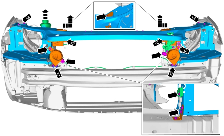
The box rests on a U-shaped aluminium bar (35mm x 80mm x 4mm, length 108cm) and is bolted down with 3 M8 countersunk bolts. The bar is mounted on the original mounting brackets of the radiator (cyan marked part in diagram). Another two countersunk M6 bolts attach the box to two latches of the bumper (just below the horns) for additional lateral stabilisation. Aside from the aluminium bar the box also rests on the thinner bar of the sub-frame (black arrows in second diagram). So the weight is distributed between the two bars.
The guy creating the box also came up with many other great ideas. E.g. we've added a lid to the upper rear side of the box to support the device board. This solved another big issue on how to mount the board in an engine compartment with almost no straight lines. Now I only have to add a couple of angles to the firewall and the entire board is sufficiently supported. The white board template is currently being converted to an aluminium board by www.fahrzeugausbau.ch. The Eberspächer heater will be mounted to the bottom side of the board, just above the motor.
So aside from a small battery box in the rear (spare tire compartment) the HV distribution is getting finalized and ready for use. With a cover for the mid-section batteries and the power-steering connected I can start to plan a test for street readiness. :) *joy*
Glasses with a metal frame dropped on battery terminals will turn into a ball of hot plasma flying in your direction.
How serious did you take these advices? Honestly? Well, I respected them partially. I've seen the spanner creating a short over the poles of one single cell (at 24:30). After 10-20 seconds it was glowing white from the heat. So I was really really careful when installing the batteries. Also when I took them out of their provisional enclosure last weekend. I held on every strap I loosened so it couldn't turn and create a short. I reminded myself at least 5 times during the first ten minutes: "Be careful! Concentrate!". And yet, I made a serious error: I removed one bolt from a strap completely and only then started loosening the second bolt. The strap slipped out of my hand and created a short with a cell in the next row - over about 15-20 cells in series. Oh my! I won't forget that crackling sound and the feeling. It' possible that I imagined it but it felt like I could feel the magnetic field. I believe it took me less than half a second to grab the strap again and break the short. The result can be seen on the pictures and the video. Fortunately just 2-3 minutes before, I put on gloves to protect my hands from physical injury (scratching those bolts can tear your skin). The copper on the straps melted immediately and sprayed around the trunk in little liquid drops. On one picture you can see them and their burn marks in the carpet of the trunk. Imagine these drops landing on the skin or worse into an eye. I was wearing only my glasses which cover only about 70% of the area. Also discovering drops of copper below the emergency vent caps of some cells and looking at the black trails on the battery casing, I consider myself extremely lucky not to have gotten injured. Once the smoke cleared from the trunk and I was sure nothing would happen any more, I had to take a walk outside - with weak knees. Next to the car stands a wagon filled with hay - imagine sparks flying over. I also remembered mounting the cells under the car. It was all done over-head, no hat, no eye protection. Believe me, I'd never do it that way again! At least a chap and full eye protection are a must - like it is for over-head welding.
Huh ? What's that supposed to mean? A depression because of battery boxes? Well.. yes and no. The reason why I didn't post for so long albeit I was celebrating a big breakthrough is the following:
As noted in my last entry, the work wasn't done yet. After the "high" from the first ride it was hard to get back and get dirty. It was more fun to take the car out for a quick spin. Then summer came, it got really hot and who wants to work in a garage with sweat dripping from your forehead at 40°C? You'd rather go to the public bath with the kids, right? Yeah.. well, all nice excuses which of course also played their part. The truth is, I got mentally blocked. I found a nice solution for the front battery box. But when placing the cardboard prototype in the engine bay, I found out there's a crumple zone which I never thought of. The beams carrying the front bumper do have some clearly visible notches which are intended to allow an easy compression and energy absorption in case of an accident. My box would fill out this entire zone with 150kg of batteries.
A friend recommended to check with the vehicle inspection first. They said that they see it as a critical topic, I should check with one of the certification agencies. They too said "It's critical" and sent me 60 pages of guidelines "Regelung Nr. 100 der Wirtschaftskommission der Vereinten Nationen für Europa (UNECE) — Einheitliche Bedingungen für die Genehmigung der Fahrzeuge hinsichtlich der besonderen Anforderungen an den Elektroantrieb", the so called ECE 100. On one page it says that either a crash test or a force equal to several tons has to be handled by the construction. Heck, how am I going to do that? I don't want to destroy my car nor any of the battery cells! I didn't get a official advice so I started thinking of alternatives. I'm not blaming any of the official agencies. Everybody was really supportive but as it's a special case probably nobody exaclty knows how to deal with such requests. All of my alternatives that came to my mind resulted in a complete re-design of the electric installation. A possibility would have been the placement of batteries behind and above the motor. But then I'd have had to move the HV-Box and all the Brusa devices to the front. A major redesign I wasn't looking forward to and which didn't promise much more success in the end.
I was sitting in the garage for hours - under and in front of the car without actually doing anything than brood and loose motivation minute by minute, not seeing any way to pass certification.
Then fortune sent me a favour: A friend gave me a nicely cut out article from a newspaper. It was about a guy in Lucerne who converted a '57 Chevy pick-up into an electric vehicle and even more: He created a professional system allowing him to use his car as source of electricity for his house, charge it with solar power and dynamically change the amount of electricity delivered from one system to the others - multidirectional. Probably the first system that works in real life and is not just some power point presentation. He's located a 30min drive from my home and also was so kind to receive me last week to explain everything he did. Result: 4 hours of techie nerd-talk :) The system he created based on Siemens technology is a real piece of art. In his garage he controls the whole system over a 17" touch screen - ease of use, statistics, full control- it's all included. But to me personally the biggest revelation was how he successfully passed inspection and got his Chevy street legal. It was a mental break-trough which made me decide to go ahead with my original design. But no, it's not 3 months lost, I also got very good advice where and how to obtain good quality battery boxes. He had his boxes created in a company located in Baar (15min drive). They're made out of welded plastic plates. The plastic and the connections are extremely robust, fire retardant and of course not conductive. Much better than any metal based construction. He told me that they made a L shaped test object and drove over it with a car. The object flattened out but did not break and restored its original shape once the force was gone. It's lighter than aluminium and can take many colours. Once I know more about it, I'll post more details.
I also bought myself a TWR JER 161 hydraulic pump used in Volvo V50. It should be possible to run it in uncotrolled mode but if you're able to send the right CAN messages, also make its power output speed dependant. It'll go into a compartment in front of the right front wheel - just like in a V50. Another device to be controlled by the GEVCU ? ;) More details can be found on DIY electric car forum.
On May, the 24th 2015 21:40 the worlds first Volvo S80 with full electric drive hit the streets. It was the maiden voyage for the car I was working on, in, above and under for the last 2 years. After a burst effort of 7days x 16hours of work, I was able to complete the tasks needed to get the car rolling. Many parts are still in a makeshift state (like the batteries in the trunk, control cables hanging loose, provisional mounting of devices, ...) but the drive unit is finished. Due to some misconfiguration on my part, the first couple of meters were accompanied with some surges and dead zones where the motor did not turn (as seen on the video where at the time I did not understand the problem). But once the car was moving, it was smooth like silk ! All you could hear is the gravel on the road and the soft hum of the coolant pump. It was perfect and the sense of delight accordingly high.
In the meantime I was able to correctly set all parameters and the car drives as reliable and smooth as a Swiss watch. Turn on ignition and one second later you're able to drive off. And keep in mind, aside from being the first electric S80 it's probably also the first converted car whose power output is controlled by interpreting CAN messages from the stock ECU. The GEVCU queries the ECU for the current throttle position and gets a response which was pre-validated by comparing the signals of two potentiometers on the throttle unit and possibly the throttle pedal too.
The car's acceleration is also very satisfying. Taking off in 1st gear people (incl. myself) are astounded, in 2nd impressed and in 3rd satisfied with normal "sedan like" acceleration. No smoking wheels, but very close and much better than I expected. Actually the 70 cells in the trunk which are held together by a clamping set only, shifted 30cm from the back of the rear seat to the rear end of the trunk. I was unable to move these 250kg back by hand.
All that's left to do now, is get the rest of the installation to production quality and street legal. Doesn't sound like much but two battery boxes are still missing, as is proper cooling, power steering and heating. Several weeks of effort - with some luck finished this year.
Note : Why the heck did I not put this onto my blog earlier ? It was in May and now it's September! I'll try to explain that in my next post.
Long time no update - sorry, I've been quite busy.
Bus Bars
As my design contained 4 bus bars with 5 connection points, I investigated alternatives to purchasing them - and spending about 400.-. Looking through the collection of left-over pieces in the metal shop, I quickly found a copper bar with a surface of 2.5 x 2.5 cm. The length was enough to be cut into 4 pieces. Costs: 40.- including 20 inox M8 screws and nuts. At www.swiss-composite.ch I bought 1L of resin they use to cover electronic parts for another 40.-. It stays flexible. Good in environments with vibrations but as I found out today, if you want to tighten the screws down, they start to slip within the hardened resin. Probably a hard one would have been better.
So, the costs were about a fifth of a retail product but the process was really fun and the "I'm proud" factor is quite significant. Check out the video how to do it.
HV Box
I'm also pretty proud of my HV distribution box. In the centre are of course the four bus bars and two contactors. On the upper/visible layer all HV connection points are made: from battery to contactors and then to motor controller and via fuses to JLD404, DC-DC converter, charger, heater. All 12V lines are immediately routed to the lower layer in order to separate the connections as good as possible (should one become loose). The main path is covered with copper bars. The low-power wires are short enough that they don't cause a short if one end comes loose. The end result is pretty heavy - about 7kg. With an aluminium L-profile on the top and bottom of the box, it was fairly easy to mount it in the car.
Motor Mount
This is definitely the area where the most effort was invested in and where the most time was lost. After spot welding all parts and then welding them down, everything got twisted and the bracket which hold the drive shaft in place no longer fit. Cut it of, weld again and then it was ok. But while the motor was resting on a block of wood on one side, I could not lift the car anymore and work almost came to a stand-still for several weeks. But now it's finished, painted black and fitting perfectly. I got some fantastic support from Peter and Reto at www.klaus-ag.ch - Thanks a lot !! Check out the video on the first spin of the wheels.
Battery Bay Construction
As I could not lift the car, finishing the battery bay under the car also had to wait. But now the final mounting brackets in the rear are in, the whole construction is rock solid.
Nordlock
When I wanted to order the Nordlock washers for the batteries, I was kindly invited for a visit to the branch in Switzerland. The sales representative wanted to do some tests with different types of washers in their lab. Although it would be beneficial to have a zink coated washer to serve as a sacrificial anode, it is not recommended. The washers don't show the nordlock effect but slip on the copper/aluminium. Also bigger washers than the screw's head is not recommendable. One might think it was because it distributes the forces more evenly. But also there the washers slipped on the copper strap instead of biting into the metal. With my CALB CA100 and copper straps, the best results were achieved with 25Nm torque and simple M8 inox washers. Refer to the video.
Battery Bottom Balancing
After having my batteries resting for 1 year with 50% SOC (from factory). most of them were in the same range with their voltage (see chart). The voltage of about 8 was considerably lower. So I suspected an internal soft short which slowly caused them to self-discharge. As I follow the philosophy of of bottom balancing and not using a battery management system (aka "battery murdering system") a internal soft short in some cells would become problematic because they would fall out of balance and be under-discharged at some point - causing damage to them and become dangerous when charging them again.
After 5-8 cycles per cell I got them all discharged to 2.750 V (+/- 0.005V). With a Cellpro Powerlab 8 it took about 2 months. A most noteworthy effect is that the cells voltage climbs up for several weeks afer a discharge. Usually around 3-8mV per week. The 8 cells with a suspected soft-short drifted downwards after a discharge (whereas the others went up). They loose about 3-30mV per week after 4 weeks. As recommended by Jack Rickard, I charged them to 4V. My theory is that the so caused volumetric expansion might brake the dendrites which cause a soft-short. The cells were charged and now discharged to 2.75V. 7 of the 8 cells are still climbing in voltage which is a good sign. One is clearly gone. 3 days after the final discharge cycle, its voltage tumbles down. This one definitely won't go into the car. The others might in an easy accessible area (for monitoring and replacement).
Battery Installation
I installed the batteries in my construction. I the exhaust pipe tunnel, I had to use a hammer to widen it a bit in order to be able to install 2 more cells. Groups of 2 or 3 cells are interconnected with cable bridges. There were a lot of space related problems in area where the gas tank was. The distance from one row of cells to the next was too small. I counted for the bolts but not the thick cable shoes and cables. As I was out of options and didn't want to give up, I had to flatten the cable-shoes. I used a parallel vise to squeeze them so they become more flat. In the process I destroyed one vise. Also about 40 of the bolt heads had to be grinded down to half of their thickness. All this caused a lot of unexpected delays. In some areas the top of the batteries/bolts/shoes/cables are in contact with the bottom of the next row of batteries. No problem regarding HV security but accessing the terminals to verify the voltage has become impossible. The batteries are fixed very well laterally. But they might jump up when driving over a bump. To prevent that, once I'm happy with the installation, I will cover the batteries with plastic and then fill the gap with expandable construction foam. Also the bottom of the construction has to be covered with plastic plates to protect the batteries from salt water and stones. I'll also have to re-route the drain of the AC system - otherwise it would drip happily on my batteries.
I was able to fit 53 cells under car. For now I will put the remaining cells into trunk - only for a couple of test drives. Then they'll have to go into a battery box in the engine compartment.
Controller Shelf
In order to envision how to mount the motor controller, dc-dc converter, charger and GEVCU, I created a prototype board out of wood. One I'm happy, it will be replaces with an aluminium plate. If somehow possible, I'll attach hinges in order to be able to lift/tilt the entire construction and reach the motor and the HV box. It's a real challenge though, as in these modern cars, there are not 90 degree angles, no straigth lines.. everything is curved.
Temperature and I/O extension for GEVCU
The GEVCU offers 8 digital outputs. Although they use MOSFET's to drive them, it's not recommended to use them to drive a Kilovac/Gigavac contactor directly - because of the high inrush current. Because of that and because I'll need more than 8 output channels, I bought myself a 16-channel relay board for Arduino Due's. They're almost free on ebay (18-36.-). This board with it's own Arduino Due will talk to the GEVCU and listen to commands via CAN bus to switch the various relays. I'll also use 4-6 single-wire temperature sensors. They will measure the temperature of the batteries in various areas. The extension box reports the temperatures via CAN bus to the GEVCU, which in order will control the charge process and not charge below 5 deg C but heat the batteries first with a water heater.
Eberspächer 6kW Water Heater
I obtained a used Eberspächer coolant water heater from a Chevy Volt with the help of Jack. It's a powerfull little box that heats with up to 6kW. It uses PTC elements where the water flows around. It's controlled via a single wire CAN. Mark Weisheimer got it running already with a play-back of recorded CAN messages from a Volt. He and others are trying to reverse-engineer the CAN messages.
Hallelujah! After installing the motor, transmission and the torque bar, after fiddling with stuck brakes on the rear wheels, after sitting around for hours and hours thinking where and how to place the batteries in the engine compartment, I thought "What the heck, let's not wait any longer until all the batteries are installed and until all the cables and switches are ready, let's install the inverter with the mains rectifier and spin up some wheels!". A bit doubtful because of my last experience with the transmission, I hooked up everything, connected the mains and the laptop, let the motor spin in neutral first and then punched in 3rd gear. No explosions, no grinding, no blown mains fuse - only wheels spinning happily. It was so quiet that at first I thought "heck, why did the motor stop now?". :) But everything was all right. Only the wheels were spinning backwards. But that's not a problem with an AC induction motor anyway. Let it run "backwards" and the wheels were spinning like they should. Shifting from 1st to 2nd and to 3rd went pretty well with the wheels in the air. The other gears needed a bit more juice on the shift knob - too much for my taste - but I think that's only because the wheels slowed down significantly while shifting. Under real driving conditions, the wheels will still be spinning through the inertia of the car. So also 5th and 6th should be possible without a clutch. (yes, I'm going clutch-less).
Still, I need some Nord-Lock washers for the batteries: Why? There's a lot of vibration in a car and I don't want the battery connections to become loose.
Unfortunately the wood shed I used as my garage caught the dry rot - that's a really nasty mildew. The entire area where it becomes visible, plus at least 1 meter of the wood has to be removed and everything else desinfected. It grows 1-4 cm per day (!) and destroys the wood so it gets soft like carton within days. All the wood and also the wall visible on this picture had to be removed in a very costly purification procedure. So half of the floor in the shed is gone now. It was renewed 1.5 years ago for 6k so it could carry the load of the car and the lift.
Bummer!


 Based on input from Walter Fassbind I contacted www.fahrzeugausbau.ch. Within a couple of weeks, they created a wonderful battery box made of black PE (poly ehtylene). The 1cm thick walls are perfect electric insulators and so strong, they hold up 9mm bullets. Once the walls are welded together, the connection is almost unbreakable. In a test with two pieces, the size of a hand, welded in a 90 degree angle, they drove over it with a car. The plates almost flatted out but didn't break and returned back to the original form almost immediately. In my opinion this is the best and safest material for battery boxes - although it doesn't stay 100% inherently stable when hot and is also inflammable, the stability is good enough and you'll have to use a bunsen burner for about 1 minute to get it burning. Plus, the box can be made 100% water proof! You can treat the material with the same tools as wood (fad, drill, knife, rasp, ...). The only down-side is that you can't glue any other material to it - but bolts for wood work very well. (sorry, it's a bit dirty on the pictures to the right)